Task
We are to control the state of three LEDs based on the values
of the two switches according to the following table:
SWITCH0 | SWITCH1 |
LED0 | LED1 | LED2 |
|---|
OFF | OFF |
OFF | OFF | OFF |
ON | OFF |
ON | OFF | OFF |
OFF | ON |
OFF | ON | OFF |
ON | ON |
OFF | OFF | ON |
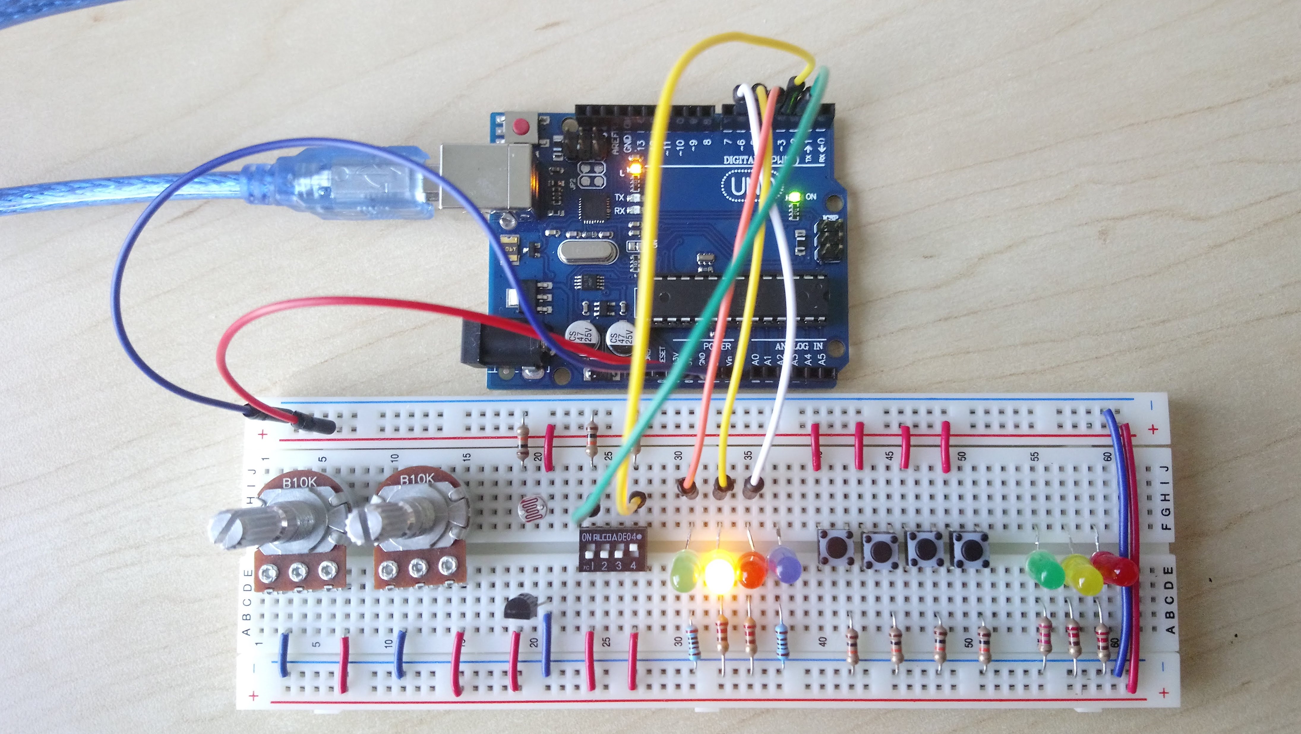
Hardware Setup
We need two switches and three LEDs. For the switches, we can use
either DIP switches, or push-buttons. The following schematic uses
DIP switches.
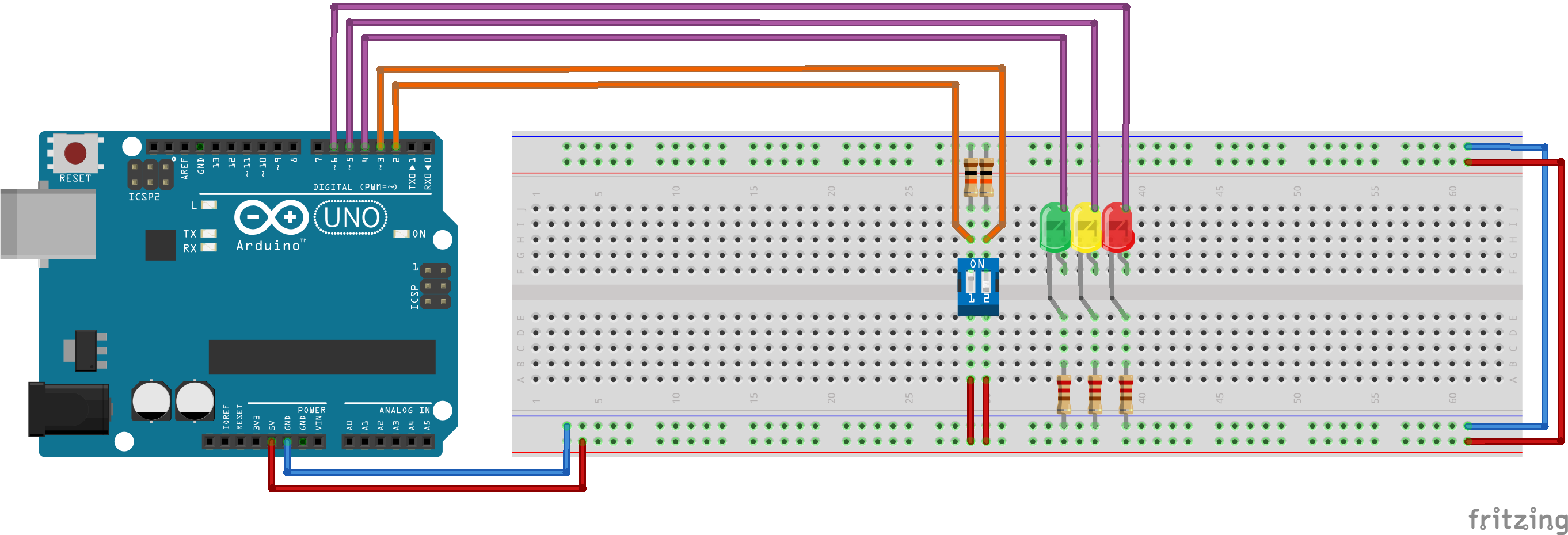
Fritzing schematic:
apsc160_sim1.fzz
| Component | Count |
|---|
| Full Size Breadboard | 1 |
| Slide DIP Switch (2 or 4 positions) | 1 |
| or Tactile Switch | 2 |
| LEDs (5 mm Round, Various) | 3 |
| 220 Ohm Resistor | 3 |
| 10 kOhm Resistor | 2 |
Software Implementation
controlLEDs.ino
